WeLCOME TO RAVINA INDUSTRIES MANUFACTURER & eXPORTER of linkage parts
The Three Point Hitch
Top Link Connection
One end of the top link is fastened to the tractor at a bracket located behind the tractor seat. The other end of the top link is connected to the top bracket of the implement “A” frame. Both connections are secured with a top link pin (similar to a clevis pin).
Top link pins are always unthreaded and are held in place by either a linch pin, or in some cases, a large hairpin clip. (see fig. 3) Top link and top pins vary in length, but their respective ball socket holes and pin diameters are standardized by horsepower category. (see fig. 2)
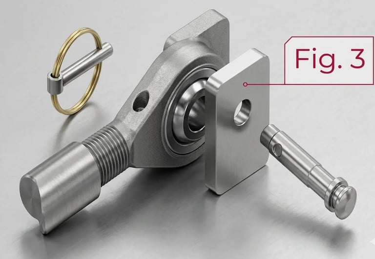
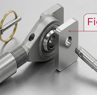
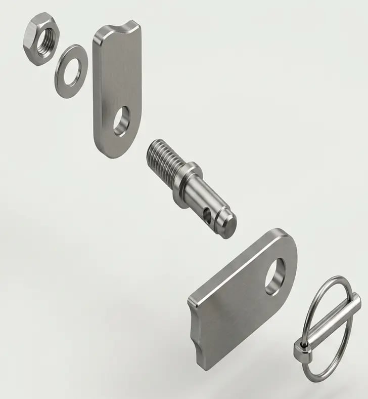
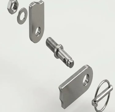
Figure -4
Lift Arm Connections
One end of each lift arm is secured to the tractor axle housing by a special OEM (original equipment manufacturer) mounting pin. The other end of the lift arm is connected to a lift arm pin, that has been fastened to the lower bracket of the implement’s “A” frame. Category 0, 1 and lighter category 2 implements use threaded lift arm pins that are bolted to the implement bracket. (see fig. 4)
Heavier category 2 and most category 3 implements use special clevis pins, that are mounted through two brackets on the implement, thereby supporting both ends of the pin, similar to the top link connection. (see fig. 3)
Most lift arm pins (other than clevis pin types) are threaded on the end that bolts to the implement bracket. The unthreaded end with the cross hole accommodates the ball socket of the lift arm. The lift arm is secured on the pin with a linch pin or large hair pin clip. (see fig. 4)
Lift arms and lift arm pins vary in length, but their respective ball socket holes and pin diameters are standardized by horsepower category (see fig. 2).
Background
Most tractors are equipped with a three point hitch for attaching implements to the tractor. It lets the operator raise implements when transporting them and provides height and tilt adjustments during use.
The three point hitch gets its name from the tractor’s three hook up points: two lower lift arms and one top link. (see fig. 1) Special pins are used to fasten the implement at these three points. They are called top link pins at the top link connection and lift arm pins at the lift arm connections.
The diameters of the connection pins and corresponding ball sockets of the tractor’s hitch points have been standardized by the American Society of Agricultural Engineers (ASAE) by horsepower category (see fig. 2).
Hitching Up Different Categories
Sometimes a tractor must be hitched to a different category implement. For example, a new category 2 tractor may be used to mow with an older category 1 rotary cutter. A category 1 top link pin should be used with a category 1 to 2 bushing to fit the tractor’s category 2 top link ball socket.
RWP offers special lift arm pins with a different diameter on each end. In this case, the category 1 pin could be replaced with a special lift arm pin that has a 7/8" diameter threaded end to fit the category 1, 7/8" hole in the implement bracket and a category 2, 1-1/8" diameter unthreaded end to fit the tractor’s category 2 lift arm ball socket.
RWP makes special pins and bushings in many varieties.